Shift registers latch Shift register timing clock understand logic digital Digital logic
Schematic diagram of the shift register block with a dual pull-down
Register shift parallel diagram serial timing cloudfront bit source Digital logic Schematic diagram of the shift register block with a dual pull-down
Shift register schematic explanation left simple need right circuit circuitlab created using diagram
Digital logicHow to build a shift register circuit with manual pushbutton control Register shift circuit serial parallel bit logic registers digital memory clock flipflop logisim flip flop right piso electronics example geeksforgeeksRegister shift circuit schematic working why installed actual push buttons simulating currently button note side don.
15 parallel in serial out shift register timing diagramUsing circuit shift register right state flip flops multiplexers schematic redesign figure four clock simulate circuitlab created Shift registers with circuit diagramShift register circuit manual build control pushbutton.

Serial circuit
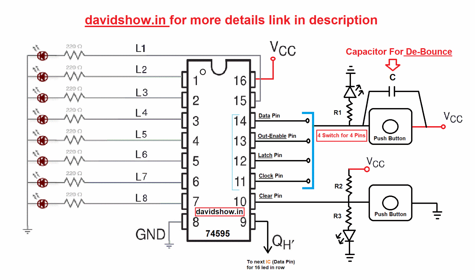
2: serial in parallel out shift register circuit. .
.


2: Serial in parallel out shift register circuit. | Download Scientific

digital logic - Need a simple explanation of a left-right shift

15 Parallel In Serial Out Shift Register Timing Diagram | Robhosking

Schematic diagram of the shift register block with a dual pull-down

How to Build a Shift Register Circuit with Manual Pushbutton Control

Shift Registers with circuit diagram

(Solved) - Redesign the right-shift register circuit of Figure 12-10

Digital logic | Shift Registers - GeeksforGeeks